Design of Structural Glass as per ASTM E1300 Standard with Numerical Example

Structural glass is an essential component in modern architecture, providing both aesthetic appeal and functionality. However, ensuring the safety and performance of structural glass elements requires precise engineering. ASTM E1300 provides guideline for the determination of the load resistance of glass in buildings. In this article, we will explore the design guideline of ASTM E1300 with numerical example, and its application in structural glass design.
Understanding ASTM E1300
ASTM E1300, titled Standard Practice for Determining Load Resistance of Glass in Buildings, provides guidelines for evaluating the load resistance and determining the center of glass deflection under various loading conditions.
Features of ASTM E1300:
- Standard method to determine the probability of breakage under load.
- Accounts for different glass types, thicknesses, and support conditions.
- Accounts long term and short term load
- Equations and charts are based on service load condition.
- Does not explicitly outlined the deflection limit of glass itself, rather provides the deflection limits of the supporting members.
- Assumes a probability of 8 lites per 1000 (0.8% breakage rate), ensuring a balance between safety and economy.
Factors Influencing Structural Glass Design
Several factors influence the strength and performance of structural glass as per ASTM E1300:
1. Glass Type and Thickness: The standard applies to different types of glass, including: Annealed glass, Heat-strengthened glass, Fully tempered glass, Laminated glass. Each type has unique mechanical properties that influence its resistance to breakage.
2. Loading Conditions: Wind load is the most critical for glass facade design. Typically design for wind governs all the time.
3. Support Conditions: The method considers different glass support configurations, such as:
- Simply supported on all four edges
- Three-edge support
- Two-edge support
- Point-supported glass systems
Step-by-Step Design Procedure Using ASTM E1300
Step 1: Define the Design Load
Determine the design load as per National Building design code. i.e., ASCE 7, BNBC 2020.
Step 2: Select the Glass Type
Choose the appropriate glass type (annealed, tempered, laminated) based on application requirements.
Pro Tips:
- Avoid annealed glass in high rise building
- Full tempered glass is strongest, but sometime it shows wave in the glass surface which creates aesthetic problem.
- On the other hand, Heat strengthened glass is the most aesthetic and moderately strong (stronger than annealed but weaker than full tempered glass).
- Therefore, on a Double Glaze Unit glass, the outer face can be considered heat-strengthened and the inner face is full-tempered.
Step 3: Choose the Glass Dimension and Thickness
Choose the glass dimension and a preliminary thickness as required by the design architect or client.
Step 4: Determine the Glass Resistance
Following the ASTM E1300 standard chart, determine Non-factored Load (NFL). Then using the Glass Type Factor (GTF) and load sharing factor (for DGU), determine the Load resistance capacity of the glass.
Step 5: Determine Center of Glass Deflection
Following the ASTM E1300 standard chart, or simply using the equation provided in Appendix X2.1, determine the center of glass deflection.
Step 6: Compare the Determined Value
Finally, compare the determined load resistance with the design load and deflection with the allowable deflection. If the load resistance capacity and allowable deflection is greater than the design load and determined deflection respectively, then the design is OK, otherwise, increase the glass thickness and repeat the design procedure.
Numerical Example
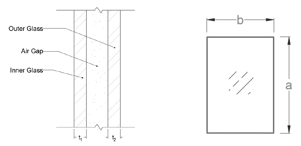
In this example we will design a simple Double Glaze (DGU) glass with equal thickness. The basic glass specs is the following -
| Glass Dimension | 2297 x 1750 mm |
| Glass Thickness | 8 mm FT + 12 mm AG + 8 mm FT |
| Glass Type | DGU, FT |
The basic design data is -
| Wind Pressure, $ P_z $ | 3.78 kPa |
| Young Modulus, E | 71700 MPa |
| Support Condition | Four Edge, Simply Support |
Check for Strength
Using the ASTM E1300 standard chart, we will determine the Non-factored Load (NFL). In this case, we will consider the probability of brakeage is 0.8%.
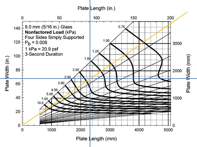
As the both inner and outer glass thickness and type is same, we can simplify the calculation for only one lite.
| Max non factored load carrying capacity of glass, NFL | 1.8 kPa |
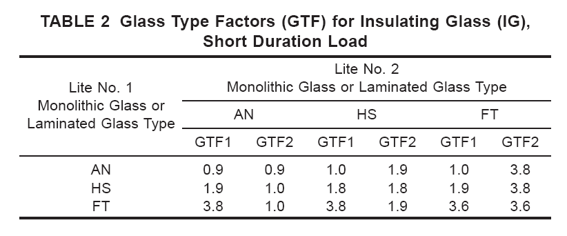
| Glass type factor, GTF | 3.6 |
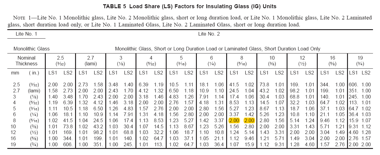
| Load sharing factor, LS | 2 |
| Load resisting capacity of the glass, LR = NFL × GTF × LS | 12.96 kPa |
| Load resistance ratio = $ P_z / LR $ | 0.29 < 1 OK |
Check for Deflection
We will use equations method to determine the center of glass deflection. For equal glass thickness and type,
| Maximum wind pressure on a single lite, $ q = \frac{P_z}{LS} $ | 1.89 kPa |
| $ r_0 = 0.553 - 3.83 (\frac{a}{b}) + 1.11 (\frac{a}{b})^2 - 0.0969 (\frac{a}{b})^3 $ | -2.781 |
| $ r_1 = - 2.29 + 5.83 (\frac{a}{b}) - 2.71 (\frac{a}{b})^2 + 0.2067 (\frac{a}{b})^3 $ | 2.091 |
| $ r_2 = 1.485 - 1.908 (\frac{a}{b}) + 0.815 (\frac{a}{b})^2 - 0.0822 (\frac{a}{b})^3 $ | 0.199 |
| $ x = ln[ln[\frac{q(ab)^2}{Et^4}]] $ | 1.536 |
| Deflection, $ \delta = t × exp(r_0+r_1 x+r_2 x^2) $ | 19.6 mm |
| Allowable deflection, $ \delta_a $ = b/60 | 29.2 mm |
| Deflection ratio, $ \delta / \delta_a $ | 0.67 < 1 OK |
Limitations of ASTM E1300
While ASTM E1300 provides a comprehensive framework, it has some limitations:
- Does not cover the effects of thermal stress explicitly.
- Not applicable for curved or highly complex glass geometries.
- Can only design rectangular glass panels. Does not account for other shaped glass.
- Assumes uniform load distribution, which may not always be accurate.
- Does not explicitly outline the deflection limit of glass itself, rather provides the deflection limits of the supporting members.
- Cannot design glass for point load (for canopy, skylight, glass floor a point load is required to apply within a small area)
Conclusion
The design of structural glass as per ASTM E1300 ensures safety and reliability in modern construction. By considering factors like glass type, loading conditions, support configurations, and probability of breakage, engineers can optimize glass structures for both aesthetics and performance. Understanding and applying ASTM E1300 is important for achieving safe and durable glass installations in buildings.
For further information, consulting the official ASTM E1300 standard and working with experienced structural engineers is highly recommended.