Design of Post‑installed Anchor as per ACI 318/BNBC 2020 – Ultimate Guide with Numerical Example
Post‑installed anchors (mechanical expansion anchors, undercut anchors, and adhesive/chemical anchors) are commonly used to attach structural and non‑structural elements to existing concrete. This guide addresses structural design of such anchors (tension, shear, combined) using the ACI 318-08 and BNBC 2020 anchorage provisions.
We cover the design process, the governing limit states, and a full numeric worked example so you can copy the workflow into your office standard checks.
Key code references and applicability
- ACI 318-08: Chapter 17 (Anchorage to concrete). ACI also references product qualification standards such as ACI 355.2 (post‑installed mechanical anchors) and ACI 355.4 (adhesive anchors). Use product systems that are qualified for the concrete condition (cracked/uncracked) per those standards.
- BNBC 2020: Appedix K of The Bangladesh National Building Code references international anchor practice; where BNBC is silent, follow ACI provisions and qualified manufacturer data, and always follow the Authority Having Jurisdiction.
> In practice: treat ACI as the technical reference for anchor limit states and BNBC as the regulatory overlay in Bangladesh.
1. Anchor bolt failure modes
- Steel strength of anchor in tension
- Concrete breakout strength of anchor in tension
- Pullout strength of anchor in tension
- Concrete side-face blowout strength of anchor in tension
- Steel strength of anchor in shear
- Concrte breakout strength of anchor in shear
- Concrete pryout strength of anchor in shear
Always check all relevant modes, do not assume steel strength controls.
Factors Influencing design capacity
- Tensile and yield strength of anchor bolt itself
- Compressive strength of concrete
- Distance from anchor bolt to concrete edge
- Anchor bolt spacing
- Diameter of anchor head
- Bond strength of adhesive (for adhesive/chemical anchor)
3. Design workflow – step‑by‑step
- Get governing loads: Extract factored loads (ultimate / LRFD or factored strength design) from structural analysis. For non‑structural elements use relevant BNBC/ACI load factors as applicable.
- Decide anchor type & manufacturer: Choose an anchor family that is qualified (ACI 355.2 for mechanical, ACI 355.4 for adhesives if required) and get the Manufacturer’s Printed Installation Instructions (MPII) and qualification data.
- Select preliminary geometry: estimate anchor diameter d, effective embedment $h_{ef}$, anchor spacing (s), and edge distances $c_a$ based on practical layout and MPII limits.
- Compute steel (anchor) strength: nominal steel strength $N_{sa}$ and shear capacity $V_{sa}$ per ACI steel equations (use manufacturer’s tensile area / strength values for post‑installed anchors).
- Compute concrete capacities:
- Concrete breakout in tension (single anchor or group) — nominal $N_{cb}$ or $N_{cbg}$
- Concrete breakout in shear (nominal $V_{cbg}$)
- Pullout strength in tension (or bond strength for adhesive anchors where relevant)
- Side-face blowout strengh in tension (typically does not governs for post-installed anchor)
- Pryout strength in shear
> Apply modifier factors for cracked/uncracked concrete, eccentricity, spacing, slab thickness etc. (ACI modification factors).
- Apply strength reduction factors $\phi$ per ACI to obtain design strengths (e.g. φ for tension anchors, for shear, for combined checks).
- Compare design capacity ≥ factored demand for each failure mode. If any mode fails, revise geometry (increase $h_{ef}$, anchor spacing, edge distance) or change anchor type.
- Combined tension + shear interaction: check interaction formulae provided by ACI when applicable (combined demand must not exceed capacity envelope).
- Serviceability & durability checks: corrosion protection, temperature, chemical exposure, cyclic loading, seismic requirements.
- Installation & QA: verify installation per MPII, torque values, hole cleaning, adhesive cure time, and periodic inspection documentation.
4. Full numerical example (step‑by‑step)
Problem statement:
Design anchor bolt for a facade mullion clump, to be anchored with post-installed mechanical anchor to a 200mm thick slab. The factored tensile load is 16.0 kN and factored shear load is 4.0 kN. Concrete is normal weight, $f'_c$ = 27.5 MPa, assume cracked at service consition. Consider 4—M12 Grade 5.8 anchor bolt with effective embedment depth of 70 mm.
The geometry of the system is following –
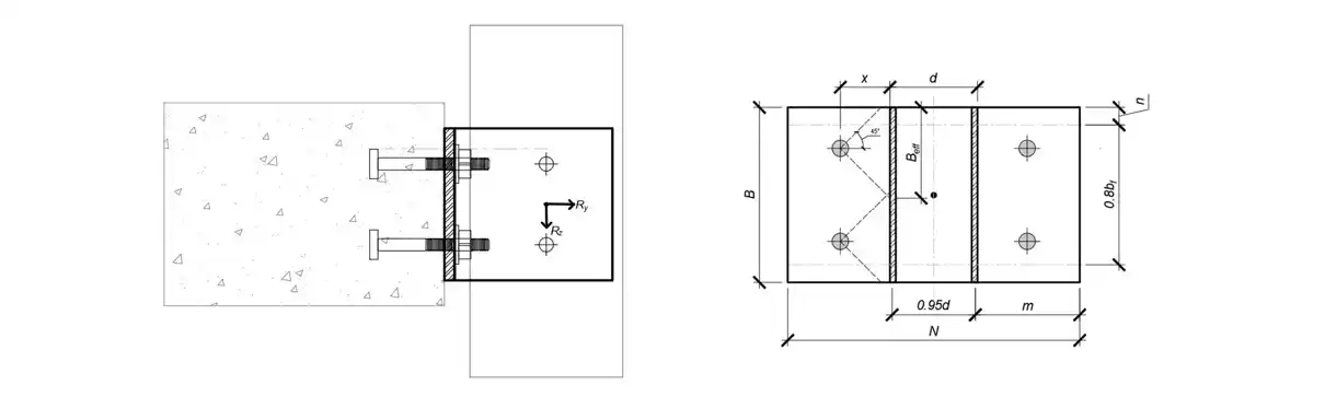
Goal: check steel strength, concrete breakout, and determine if the anchor is OK or needs revision.
Step 1 – Design data and load analysis
Diameter of anchor bolt, $d_a$ = 12 mm
Effective embedment length, $h_{ef}$ = 70 mm
Compressive strength of concrete, $f'_c$ = 27.5 MPa
Yield strength of anchor, $f_y$ = 400 MPa (Grade 5.8)
Tensile strength of anchor, $f_u$ = 500 Mpa (Grade 5.8)
Applying the equations of static equilibrium: $ \sum F_y^{→+}=0, \sum F_z^{↑+}=0 $,
> Tension force, $R_y$ = 16.0 kN
> Tension force in single bolt = 16.0/4 = 4.0 kN (No. of anchor bolt = 4)
> Shear force, $R_z$ = 4.0 kN
> Shear force in single bolt = 4.0/4 = 1.0 kN
Step 2 – Steel strength in tension
$\phi N_{sa} = \phi · A_{se,N} · f_{uta}$ (kN) (Eqn. 6.K.3, BNBC 2020)
Where
$\phi$ – Strength reduction factor
$A_{se,N}$ – Tensile stress area ($mm^2$)
$f_{uta} = min(860, 1.9f_y, f_u)$ – Allowable tensile strength of anchor (MPa)
$N_{ua}$ – Tension force in single anchor (kN)
$\beta$ – Capacity ratio
| $\phi$ | $A_{se,N}$ | $f_{uta}$ | $\phi N_{sa}$ | $N_{ua}$ | $\beta_N$ | $Check$ |
|---|---|---|---|---|---|---|
| 0.75 | 84.3 | 500 | 31.6 | 4.0 | 0.13 | OK |
Step 3 – Concrete breakout strength in tension
$\phi N_{cbg} = \phi · (\frac{A_{NC}}{A_{NCO}}) · \psi _{ec,N} · \psi _{ed,N} · \psi _{c,N} · \psi _{cp,N} · N_b$ (kN) (Eqn. 6.K.5, BNBC 2020)
Where
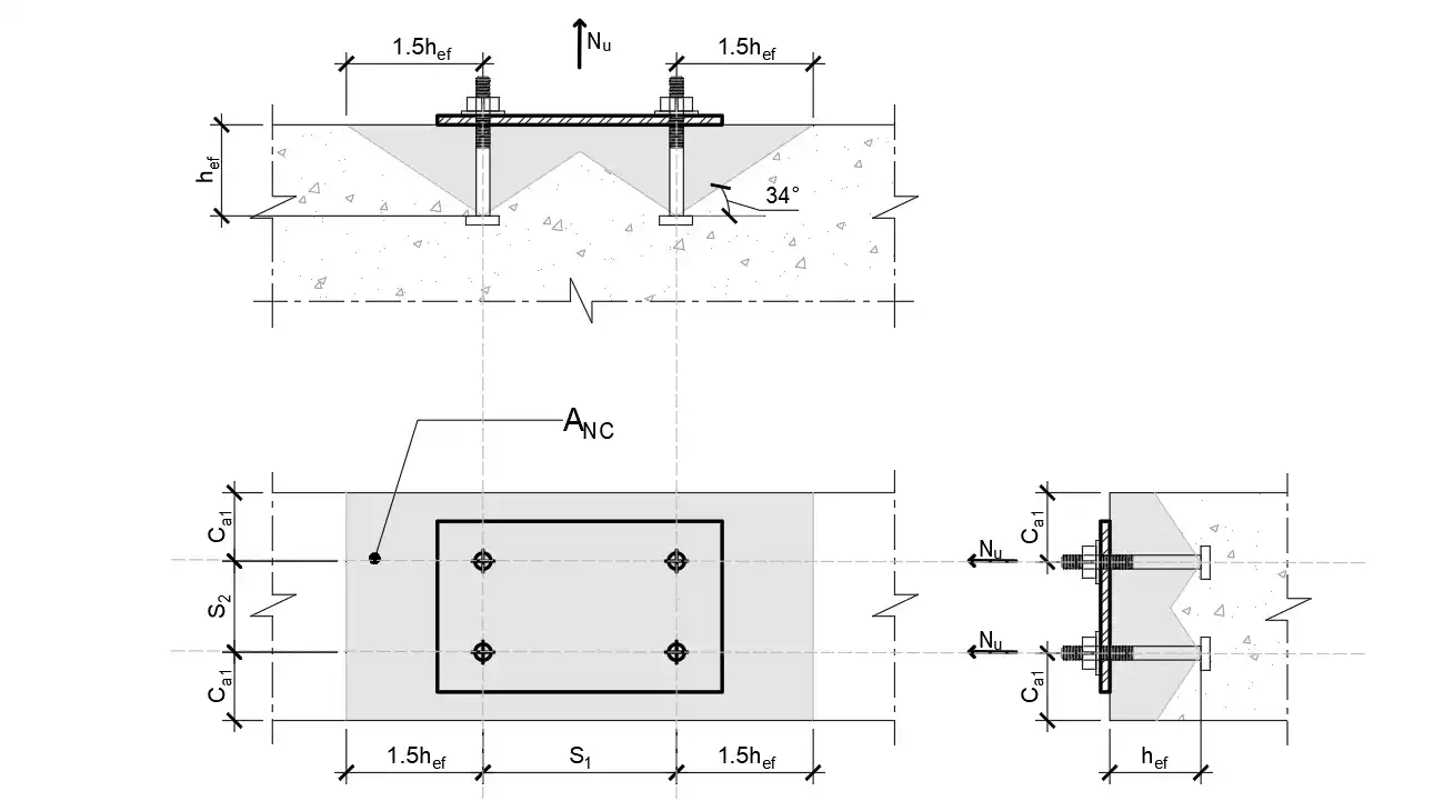
$A_{NC}$ – Concrete failure area for anchor group ($mm^2$)
$A_{NCO} = 9 h_{ef}^2$ – Conc. failure area of single anchor w/o edge influence ($mm^2$)
$\psi _{ec,N}$ – Modification factor for eccentricity
$\psi _{ed,N} = min(0.7 + \frac{0.3 C_{a,min}}{1.5 h_{ef0}}, 1})$ – Modification factor for edge distance
$\psi _{c,N}$ – Modification factor for concrete condition (cracked)
$\psi _{cp,N}$ – Modification factor for post-installed anchor (cracked)
$N_b = k_c · \lambda · \sqrt{f'_c} · h_{ef0}^{1.5}$ – Basic concrete breakout strength (kN)
$k_c$ – Installation type factor
$\lambda$ – Modification factor for light-weight concrete
$N_{ug}$ – Tensile force in group of anchors (kN)
| $\phi$ | $A_{NC}$ | $A_{NCO}$ | $C_{a,min}$ | $\psi _{ec,N}$ | $\psi _{ed,N}$ | $\psi _{c,N}$ | $\psi _{cp,N}$ | $k_c$ | $\lambda$ | $N_b$ | $\phi N_{cbg}$ | $N_{ug}$ | $\beta_N$ | $Check$ |
|---|---|---|---|---|---|---|---|---|---|---|---|---|---|---|
| 0.65 | 78000 | 44100 | 60 | 1.0 | 0.87 | 1.0 | 1.0 | 7 | 1 | 21.5 | 21.5 | 16.0 | 0.74 | OK |
Step 4 – Pullout strength in tension
$\phi N_{pn} = \psi · \psi _{c,p} · N_p$ (kN) (Eqn. 6.K.14, BNBC 2020)
Where
$\psi _{c,p}$ – Modification factor for concrete condition (cracked)
$N_p$ – Basic concrete pullout strength (5% fractile test, ACI 355.2) (kN)
| $\phi$ | $\psi _{c,p}$ | $N_p$ | $\phi N_{pn}$ | $N_{ua}$ | $\beta_N$ | $Check$ |
|---|---|---|---|---|---|---|
| 0.7 | 1.0 | 20.0 | 14.0 | 4.0 | 0.29 | OK |
Step 5 – Concrete side-face blowout strength in tension
Splitting during installation rather than side face blowout strength governs post-installed anchor. Ref. Sec. K.5.4, BNBC 2020.
Step 6 – Steel strength in shear
$\phi V_{sa} = \phi · A_{se,V} · f_{uta}$ (kN) (Eqn. 6.K.19, BNBC 2020)
Where
$\phi$ – Strength reduction factor in shear
$V_{ua}$ – Tension force in single anchor (kN)
| $\phi$ | $A_{se,V}$ | $f_{uta}$ | $\phi V_{sa}$ | $V_{ua}$ | $\beta_V$ | $Check$ |
|---|---|---|---|---|---|---|
| 0.65 | 84.3 | 500 | 16.4 | 1.0 | 0.06 | OK |
Step 7 – Concrete breakout strength in shear
$\phi V_{cbg} = \phi · \frac{A_{VC}}{A_{VCO}} · \psi _{ec,V} · \psi _{ed,V} · \psi _{c,V} · \psi _{h,V} · V_b$ (kN) (Eqn. 6.K.22, BNBC 2020)
Where
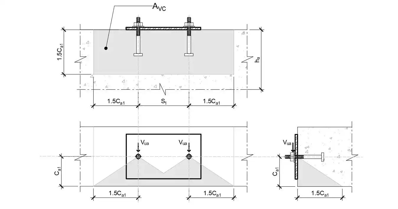
$A_{VC}$ – Concrete failure area for anchor group $(mm^2$)
$A_{VCO} = 4.5 C_{a1}^2$ – Conc. failure area of single anchor w/o edge influence ($mm^2$)
$\psi _{ec,V}$ – Modification factor for eccentricity
$\psi _{ed,V} = min(0.7 + \frac{0.3 C_{a2}}{1.5 C_{s1}, 1})$ – Modification factor for edge distance
$\psi _{c,V}$ – Modification factor for concrete condition (cracked)
$\psi _{h,V} = max(\sqrt{\frac{1.5 C_{a1}}{h_a}}, 1)$ – Modification factor for concrete depth $h_a < 1.5 C_{a1}$
$V_b = 0.6 (\frac{l_e}{d_a})^{0.2} · \sqrt{d_a} · \lambda · \sqrt{f'_c} · (C_{a1})^{1.5} $ – Basic concrete breakout strength of single anchor (kN)
$l_e = min(h_{ef}, 8 d_a)$ – Load bearing length of anchor for shear (mm)
$V_{ug}$ – Shear force in group of anchors (kN)
| $\phi$ | $A_{VC}$ | $A_{VCO}$ | $C_{a1}$ | $C_{a2}$ | $h_a$ | $\psi _{ec,V}$ | $\psi _{ed,V}$ | $\psi _{c,V}$ | $\psi _{h,V}$ | $l_e$ | $V_b$ | $\phi V_{cbg}$* | $V_{ug}$ | $\beta_V$ | $Check$ |
|---|---|---|---|---|---|---|---|---|---|---|---|---|---|---|---|
| 0.7 | 32400 | 16200 | 60 | - | - | 1.0 | 1.0 | 1.0 | 1.0 | 70 | 7.2 | 10.1 | 2.0 | 0.2 | OK |
*2 Two bolts in bolt group
Step 8 – Concrete pryout strength in shear
$\phi V_{cp} = \phi · k_{c,p} · N_{cp}$ (kN) (Eqn. 6.K.31, BNBC 2020)
Where
$k_{c,p}$ – Concrete pryout factor
$N_{cp} = N_{cbg}$ – Concrete breakout strength in tension (kN)
| $\phi$ | $k_{c,p}$ | $N_{cp}$ | $\phi V_{cp}$ | $V_{ug}$ | $\beta_V$ | $Check$ |
|---|---|---|---|---|---|---|
| 0.7 | 2 | 33.1 | 46.4 | 2.0 | 0.04 | OK |
Step 9 – Interaction of tensile and shear force
$\beta_{NV} = (\beta_N)^{\zeta} + (\beta_V)^{\zeta}$ (Sec. K.7, BNBC 2020)
Where
$\beta_N$ – Highest design ratio from all tension failure mode
$\beta_V$ – Highest design ratio from all shear failure mode
| $\beta_N$ | $\beta_V$ | $\zeta$ | $\beta_{NV}$ | $Check$ |
|---|---|---|---|---|
| 0.74 | 0.2 | 1.67 | 0.68 | OK |
5. Installation, QA & manufacturer instructions
- MPII (Manufacturer’s Printed Installation Instructions) are mandatory per ACI. They govern hole size, hole cleaning method (brush & blow or vacuum), adhesive injection technique, installation torque, torque‑tightening after curing, and curing time.
- Testing & qualification: use anchors tested to ACI 355.2 (mechanical) or ACI 355.4 / ICC‑ES acceptance criteria (adhesives) for seismic and cracked‑concrete use.
- Inspection: verify hole drilling, cleaning, embedment depth, and torque using a checklist. Keep photos and torque logs.
6. Common pitfalls & practical tips
- Don’t assume pullout controls, often concrete breakout or steel controls. Check all modes.
- Edge/spacing: anchors close to edge or tightly spaced reduce breakout area dramatically, check ACI group modifiers.
- Bonded anchors need hole cleaning, installers often skip vacuum cleaning and then complain about failures.
- Seismic & cyclic loads: use products qualified for cracked concrete and dynamic loading; adhesive systems without cyclic qualification may fail.
- Use manufacturer calculators for initial sizing as they’re conservative and fast. Always document and cross‑check with ACI.
- If steel ≤ concrete capacity → increase anchor diameter or use multiple anchors.
- If concrete governs → increase embedment $h_{ef}$, increase edge distance, or use larger spacing/group arrangement.
- Always verify adhesive cure times and temperature limits from MPII.
On this page
- Step 1 – Design data and load analysis
- Step 2 – Steel strength in tension
- Step 3 – Concrete breakout strength in tension
- Step 4 – Pullout strength in tension
- Step 5 – Concrete side-face blowout strength in tension
- Step 6 – Steel strength in shear
- Step 7 – Concrete breakout strength in shear
- Step 8 – Concrete pryout strength in shear
- Step 9 – Interaction of tensile and shear force
Comments (4)
Casino deposits. offers fast and secure transactions, making it ideal for Casinors. minimum deposits starting at $1, to gaming platforms globally.
Enjoy seamless gaming with <a href=https://luckspire-review.com/>casino deposit from 1 dollar paypal</a> options available now!
attracts additional Casinors. Connecting your card in Apple Pay, eliminating repeated sharing of private details. across multiple Casino providers.
Sprawdz najlepsze <a href=https://www.kasyna-pl-bez-depozytu.pl/>kasyna bez depozytu z bonusem powitalnym</a>, ktore oferuja wyjatkowe promocje dla nowych graczy.
Przed skorzystaniem z bonusa warto sprawdzic warunki jego wykorzystania, by nie natknac sie na ukryte ograniczenia.
Sprawdz najlepsze <a href=https://www.kasyna-pl-bez-depozytu.pl/>kasyna bez depozytu z bonusem powitalnym</a>, ktore oferuja wyjatkowe promocje dla nowych graczy.
Warto jednak dokladnie zapoznac sie z regulaminem takich ofert, aby uniknac nieprzyjemnych niespodzianek.
Sprawdz najlepsze <a href=https://www.kasyna-pl-bez-depozytu.pl/>kasyna bez depozytu z bonusem powitalnym</a>, ktore oferuja wyjatkowe promocje dla nowych graczy.
Urozmaicona oferta umozliwia dopasowanie promocji do wlasnych preferencji i stylu gry.
Leave a Comment